Background
Update 2020: Several people have asked for the firmware source code,
and you can now find the code on GitHub. It
ain't pretty, but should give you an
idea of how this whole thing fit together.
After building the nixie tube alarm clock, which
incorporates a bright,
self-dimming light intended to wake me up gently, I wanted to use it to
induce a lucid dream state [1]. I tried rapidly flashing the bright
light at around 5 AM, hoping it would coincide with a dream, but I had
little luck. I had to be able to detect REM sleep in order to affect my
dreams, as most dreams occur in the REM phase of sleep.
The method of using flashing lights to stimulate a person in REM-sleep
has been shown to be effective by several researchers [2]. In one study,
flashing lights were administered through goggles worn by the sleeper,
inducing lucidity 33 times over a total of 58 nights with 44 subjects
(LaBerge, Levitan, Rich, & Dement, 1988) -- many of which had never
experienced lucid dreams prior to the study. I urge you to look at
LaBerge's article if you find this interesting, it is a wonderful read.
The more successful trials use various methods of electrophysiological
techniques (i.e. EEG, EOG, EMG, MRI etc.) to detect rapid eye movement
(REM) sleep in the subject and then stimulating their eyes with flashing
lights. The lights would often manifest themselves in the subject's
dreams as howling ambulances, lightning and such, which indicated to the
subject that they were indeed dreaming, thus entering a lucid state.
This seemed like a promising place for me to start. I am also planning
to use aural stimulation by playing Edith Piaf's
Non, Je Ne Regrette Rien (as made famous by the movie Inception),
because it would be
awesome
to enter a lucid dream state on her que.
I went on to ask my mother, who used to work with EEG equipment back in
the day, if she had any electrodes or other equipment of interest laying
around. She did, and I managed to procure two EEG caps, some adhesive
conductive electrode paste and a rather nasty abrasive compound. After
studying the possible methods through which one can detect REM sleep, I
settled on electrooculography (EOG) as my method of detection [3], as it
looked fairly straightforward.
What is electrooculography, and how do you use it?
I'm glad you asked. This wonderful article
explains everything in
detail. Long story short: There is a standing potential in your eye
between the cornea and the retina, which is in the range of 0.4-1.0 mV.
This potential is caused by the higher metabolic rate in your retina.
Biology aside, this means that every time you move your eyes, you are
also changing the surface potential of the skin surrounding your eyes.
This potential change is measurable, though you need a good electrical
connection between your electrodes and the skin in order to suppress
noise and allow the voltages to be visible. You also need a large
amplification factor in order to be able to read this voltage with a
"mortal" ADC like the ones you'll find in the generic MCUs.
Research and decisions
Naturally, I am not the first to think of doing this kind of experiment. I
stumbled across Jona Frank and Pranav Ravichandran's article on logging
EOG data with an Arduino for a simple BCI system, as well as
chipstein's Google Site regarding EOG in general and a few methods
of home-use [4][5], collecting ideas for circuit designs. Their approaches
are similar in design in that they use an
instrumentation amplifier
as
a preamplifier stage
before they drive the signal through some heavy filters, and finally
amplifying the signal further with generic opamps. A big thanks goes to
these guys for documenting and publishing their work for the general
public.
I figured that, since I am not interested in the eye's absolute position
in reference to the skull, three electrodes would suffice: One reference
electrode on my forehead and two electrodes at either temple. This method
restricts the system to being sensitive to lateral eye movement only, but
after a rather disturbing YouTube session of watching people experiencing
REM sleep, I decided that lateral eye movement would probably be enough to
determine whether or not I am experiencing REM sleep.
It was necessary to rip open the electrode caps I had in order to extract
the electrodes, which seem to consist of some semi-pliable metal which
most likely offers excellent conductivity. The electrode paste, when
sandwiched between my skin and the electrode disk, makes a great basis for
EOG measurements. Without paste, the resistance between my temples were in
the order of megaohms. With the paste and a tight headband to keep
everything in place, I was down below 10 kiloohms, exactly where I wanted
to be -- even in spite of the fact that the paste expired in '87. This
stuff is fascinating.
Fastening the electrodes to my skin was initially done (rather crudely) by
means of scotch tape and a hedband to keep everything in place. I later
moved to using stretchy band aids and paper padding which greatly improved
comfort and system stability (noise and baseline offsets from breathing
and tossing about in bed). The abrasive compound does an excellent job of
lowering the electrode impedance to well below 3 kΩ, but after getting a
heavy rash on my temples and forehead, I switched to simply scrubbing the
electrode sites with warm water. This does increase electrode impedance
somewhat, but at least my skin won't fall off.
I also made a fun discovery: When I put the multimeter in continuity mode
and measure across the electrodes in my temples, I can clearly see rapidly
flashing lights emanating from the corners of my eyes. The effect persists
if I close my eyes. This must mean that the weak current from the
multimeter is stimulating the optic nerve somehow. It would be cool to
directly stimulate the optic nerve in order to induce the flashing lights,
but I am not sure sending current through my head is the best idea. I am
learning all sorts of trivia about human biology through this project.

Electrodes, conductive paste and an abrasive compound (which gave me a
nasty rash)
Initial design, breadboarding and testing
After diligently taking notes from the aforementioned articles and
simulating everything in LTspice along the way, I designed the following
circuit in CadSoft Eagle:
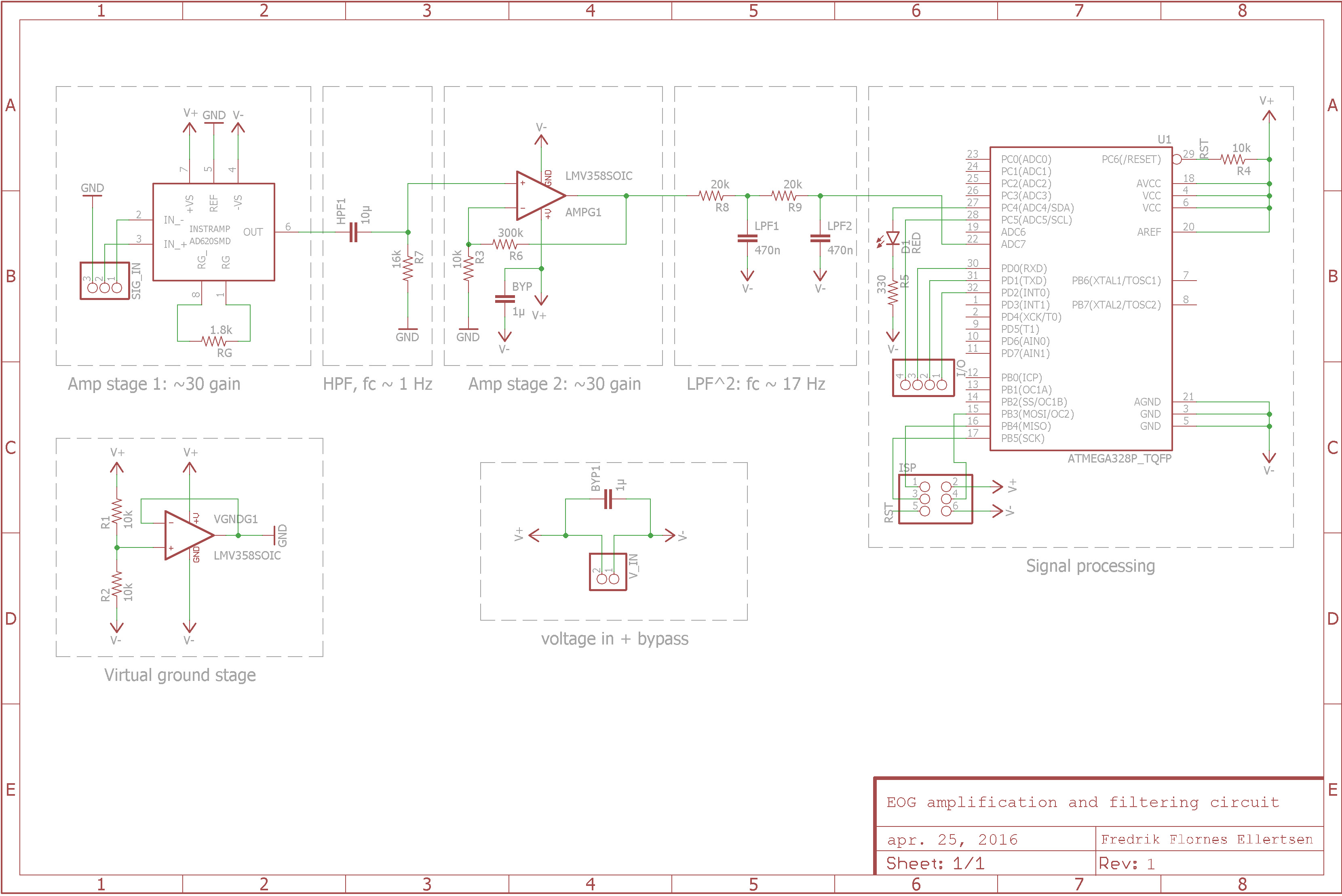
I went with the
AD620,
a readily available instrumentation amplifier,
as my preamp stage amplifier (I later changed this to the
INA126PA
which offers similar electrical characteristics, identical pinout but uses
a different gain calculation). Apart from the electrodes and conductive
paste, this SOIC is probably the single most expensive part of the project
(my dignity not included). The resistor between the Rg
pins set the gain of the amplifier to around 30. The signal is then high
pass filtered with a 1st order HPF with a cut-off frequency of
around 1 Hz. I chose to high-pass filter the signal here rather than at
the end of the amplification track because simulation of the circuit in
LTspice claimed that the latter choice would be unstable and prone to
noise. Breadboard testing confirmed this. The signal is then amplified in
a non-inverting amplifier with a gain factor of around 30 before it is
passed through a 2nd order LPF with cut-off at around 17 Hz. This brings
the total theoretical amplification of the circuit, not accounting for the
filtering, to around 900.
All amplification and filtering is done in reference to virtual ground
(denoted GND in the schematic above) which is generated by a voltage
divider and a voltage follower. GND is also connected to the reference
electrode in my forehead, thus grounding the circuit to my "baseline skull
potential". The amplified and filtered signal is fed into the ADC of an
ATMega168. According to LTspice, there should be very little harmonic
distortion through the circuit. During initial tests I was using an
Arduino Uno and a Diligent Analog Discovery 2 to program, probe, test and
debug my circuit.
I was struggling with 50 Hz noise from the mains grid, as one generally
does in high-gain circuits. Adding higher orders to my LPF was possible,
but I found a much cleaner solution: I set the sample frequency of the
ADC to 50 Hz, effectively rendering the noise moot. The 50 Hz noise is
aliased into a DC (or a slow sine due to inaccuracies in the frequency
from internal/external oscillators) which is killed by the aggressive 1 Hz
high pass filter in my circuit. The EOG signals, ranging from around 3 to
10 Hz, are not affected as the sample frequency is well above the Nyquist
frequency. This helped a great deal with all the noise my breadboard
monster picked up.
One of the great aspects of differential amplifiers is that the signal
wires, though only conveying millivolts, can be several meters long
without much additional noise appearing in the circuit. Any induced emf on
the signal wires will be equally distributed over the wires, thus
cancelling it out. Hooking the electrodes to the breadboard with ribbon
cable, I was able to sleep with the system logging my eye movements
through
PuTTY. This allowed
me to study trends, amplitudes and
timings, and devising a detection algorithm.
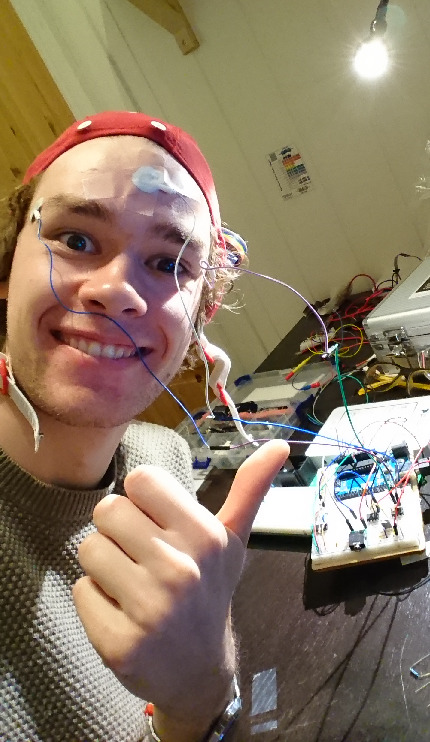
Initial testing was not pretty. It was effective, though.
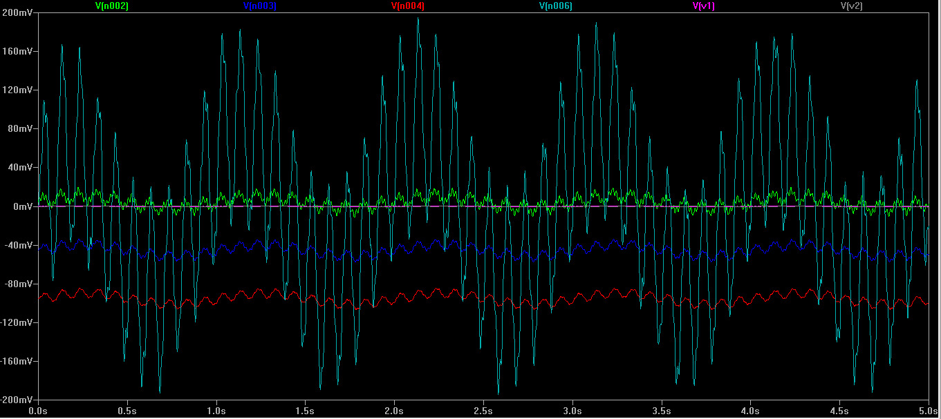
LTspice simulation of the circuit. Input signals are in the order of 0.5
mV and are simulated with noise in the 30-50 Hz range. The green, blue, red
and finally white signals are probed from successive points in the
amplification stages.
PCB design
Parallel to breadboard testing, I designed the circuit board with noise
suppression in mind, trying to follow general guidelines for analog
high-gain circuit design and PCB layout [6]:
- Keep signal tracks short
- trace width is .3048 mm, the smallest tolerance I can reliably
handle with the laser etch method
- Keep analog and digital tracks well seperated
- I left a large gap between analog circuitry on the left and
digital circuitry on the right
- Keep analog and digital ground seperated
- Don't run analog traces perpendicular to any noisy trakcs (e.g.
RX/TX)
- the final analog trace is running diagonally through the board
- Use bypass capacitors where needed
- 1 µF caps scattered throughout
Here is the layout I settled on:
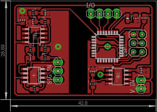
Top view: Flodded plane carries V-. V+ is traced along the
perimeter and is fed to the ATmega through a via and a trace on the bottom
layer.
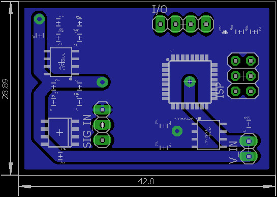
Bottom view: Flooded plane carries GND. Vias and traced allow
current to be sinked from amplifier stage, well away from the digital part
of the circuit.
The datasheet of the ATmega168 calls for an LC network supporting AREF
pin, which I did not realize until after producing the circuit board. It
doesn't seem like a problem, though; The ADC readings seem stable. I
struggled a lot with the etching process. On my fourth try I succeded.

The finished PCB. Note the bodge on the voltage follower -- I had flipped
the opamp in the schematic. It's fixed in the version provided.

One of the several failed etches. This method is very unforgiving.
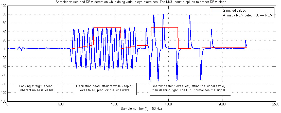
Results: Eye movement detection works!
The PCB proved to be much less noise-riddled than the breadboard test
(unsurprisingly). Below you see the data from a short session of
eye-exercises (blue) as well as the data from my REM sleep detection
algorithm (red). This data validates the success of the amplification
circuit as well as the feasibility of a reliable "eye movement" detection
algorithm.
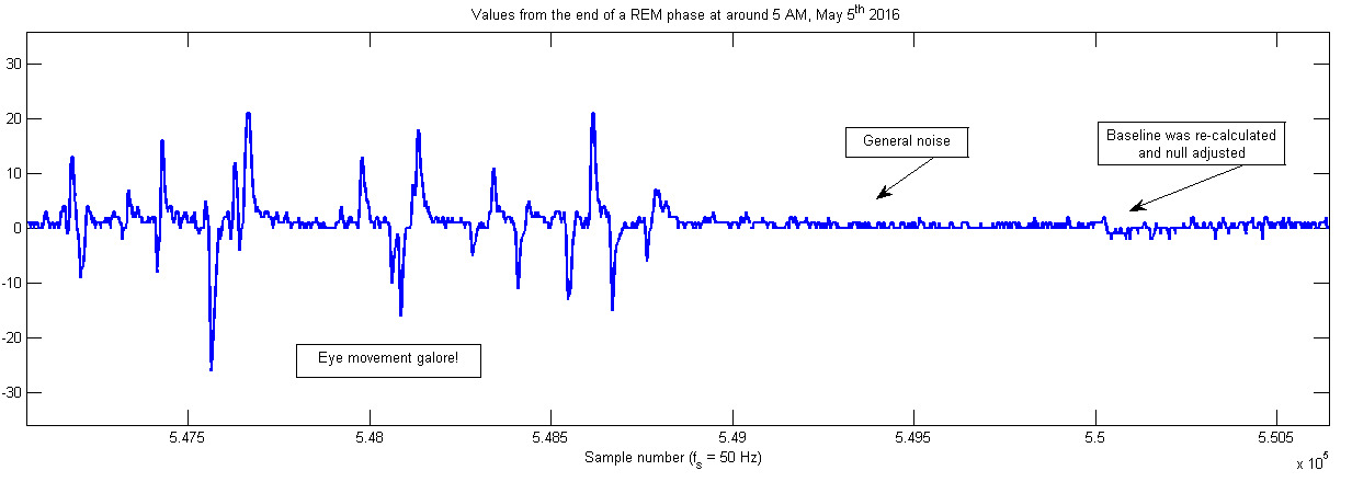
Below you see data from the morning of May 5th, showing what
both I and my REM detection algorithm agree is the end of REM phase. Click
image to expand.
Lucid dreaming induction by flashing lights
At this stage in the project (May 15) I have a fairly reliable detection
algorithm for REM sleep. I ordered some some bright, 0.5 W warm white SMD
LEDs from eBay, and have implemented them into the system. They are sewn
into the front part of the headband, and lie just a few millimeters away
from my eyelids when I pull the mask down to sleep. The lights are flashed
rapidly for 10 seconds whenever the ATmega decides that I am in REM sleep.
After sleeping with the system every night for nearly two weeks, though, I
have yet to experience any lucid dreams or even remembering the flashing
lights the morning after. The photo on the right shows the brightness of
the LEDs, and I find it truly astonishing that I can sleep through such
relentless visual noise without waking up. It's frustrating knowing that
the system works perfectly, and that the problem is in the driver's seat.
I think it's time to rethink my method of induction.

The lucid induction LEDs are fairly bright...
...flashing lights didn't work. We need Edith Piaf.
I have huge hopes for music-induced lucid dreaming -- there must be a
reason why the production team behind Inception opted for audio rather
than light for communicating through the dream levels! I have therefore
written a short Python program which captures the serial data over USB and
uses the VLC package to play a 30 second snippet of 'Non, Je Ne Regrette
Rien' when the ATmega detects REM sleep. Below you see an image of the
system as it is today (Sep. 19) after I added a 3.5 mm audio cable to the
umbilical cord which connects the system to my computer. It consists of
cables en masse, and the umbilical cord running from my head to my
computer is getting rather unweildy. I'd love to redesign the project and
base it around Bluetooth instead, eliminating all these pesky cables.
My main problem these days is Windows 10. No matter what I do, my computer
decides to go to sleep after about half an hour after I go to sleep. Some
update has wrecked the power management settings in the OS. This ruins my
data logging, of course. It's now September 19, and I'm still fiddling
with the settings.
On the upside, though, I have acquired some proper ECG electrodes from 3M
which eliminates the hassle of electrode paste and band-aids. I will give
them a go tonight.
Discontinuing mark I of the system
I hate to admit it, but the system has gotten out of hand. There are too
many weak points, in particular along the umbilical cord which connects it
to the computer. Furthermore, the PCB I etched the circuit onto seems to
be of low quality, and the copper plating has started to lift from the
fiberglass in certain places (this might be related to the fact that I
omitted all forms of strain relief on the cables, heh). A complete
redesign is needed, and that's what I intend to do!
The new 3M electrodes work fantastically though, and I have recently been
tinkering with the post-processing of the sleep data. Most notably I am
using MATLAB to convert the raw ADC data into WAV which Audacity is more
than happy to analyse. Previously I have loaded the CSV file directly into
MATLAB and used the native plot functionality which is extremely
sluggish both at laoding the data and at displaying it. The new method,
though, can run through 4.1 million lines of CSV data and spit out a WAV
file in less than 10 seconds. Not only is it significantly faster, but it
allows me to perform more in-depth analysis of the data using tools
intended for audio processing. Furthermore, I can listen to my eye
movement activity if I crank the sample frequency into the audible regime.
It's really bizarre.
Mark II of the lucid dream induction system will be based around
BLE to
get rid of all those cables. Stay tuned!
Side note: Data from stand work (interesting statistics)
On the 28th of April our study programme held a stand at NTNU
presenting ourselves to visiting High School students. One of my class
mates and I were in charge of the stand, and I wore the EOG system as a
way to demonstrate what one might expect to learn and do while studying
ELSYS. I had a large computer monitor showing an oscilloscope trace
from the last stage of the amplification circuit as well as the flowing
data from the ATmega on-screen. The students were very intrigued
(especially when I explained that I was trying to hack my dreams,
Inception style), and it was a lot of fun.
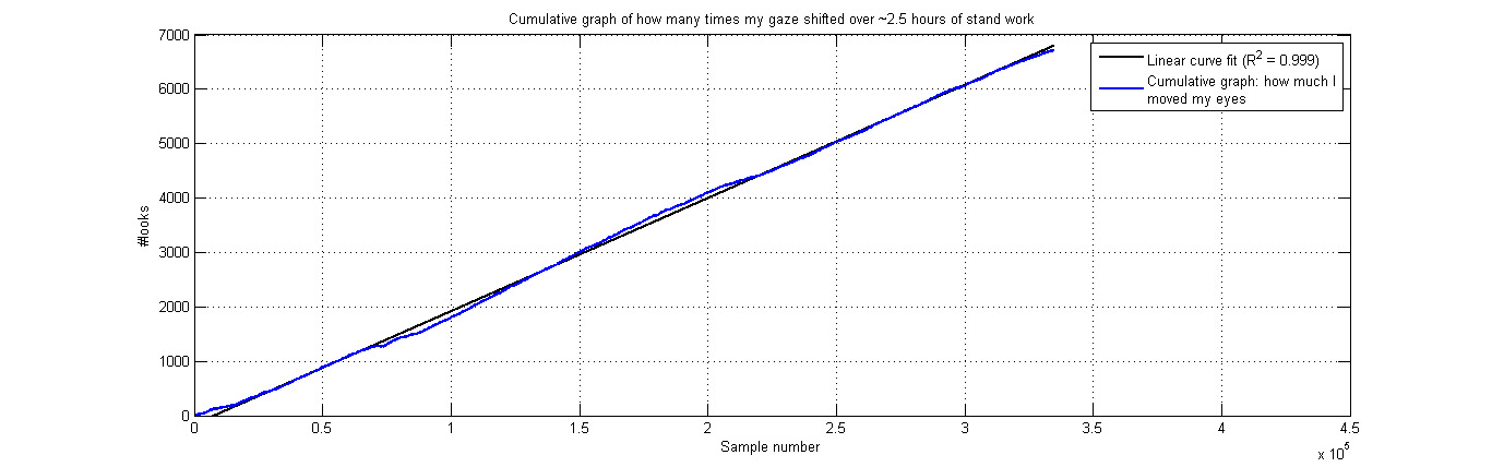
After the stand I realized that PuTTY had logged everything my eyes did
over the course of the ~2.5 hours we worked there, and the data is
fascinating. I moved my eyes
no less than 6715 times. A "move" was defined as an analog spike
with an amplitude equal or greater to 17 from the ATmega ADC, which
roughly equates to moving my eyes halfway across the screen of a 15.6"
laptop at a comfortable distance. Below is an excerpt of the eye movement
data (left) and the cumulative "gaze shift counter" (right). Click images
to expand.
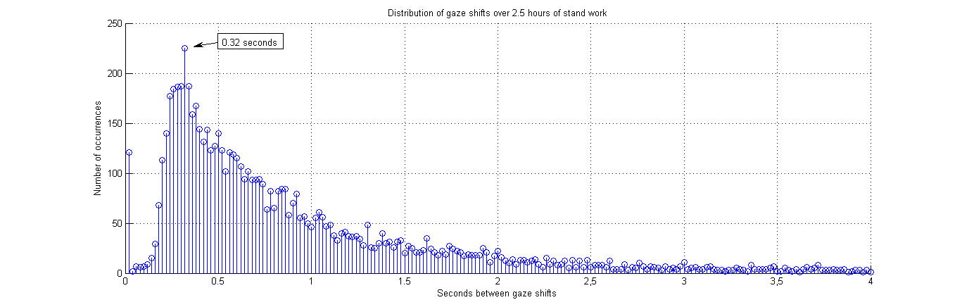
I also plotted the distribution of gaze shifts by how long time intervals
there were between them, expecting the data to be normally distributed.
Instead, it seems that the gaze shifts follow some sort of gamma
distribution. I later learned that waiting-time processes generally follow
such a distribution. I have no idea what to do with this data,
though.
Click here to
download the raw data (373 kB .rar). Please contact me if you find
anything interesting in the
data set.
Links & references
[1] Lucid dreaming: https://en.wikipedia.org/wiki/Lucid_dream
[2] Stephen LaBerge, Ph.D. Psychophysiological Studies of Consciousness
during REM Sleep.
http://www.lucidity.com/SleepAndCognition.html
[3] Article explaining the basics of electrooculography:
http://www.bem.fi/book/28/28.htm
[4] Jona Frank and Pranav Ravichandran. Tracking Eye movement with an
Arduino and a Computer.
http://onloop.net/hairyplotter/
[5] "chipstein". Homebrew Do-it-yourself EEG, EKG, and EMG.
https://sites.google.com/site/chipstein/home-page
[6] Ron Mancini, Editor in chief, TI. Op Amps For Everyone
http://web.mit.edu/6.101/www/reference/op_amps_everyone.pdf