For the past few months (feb. 2016) and over around 200 hours I have been designing and building a
nixie-based alarm clock. The inspiration came from
those wake-up light clocks that slowly brighten a powerful light source before waking you up in
order to trick the brain
into thinking it's morning. That was early September 2015, and I think it's safe to say that the
project escalated quite a
bit. When I miraculously salvaged four
Amperex ZM1000 nixie tubes in November from a dumpster and managed to
bring them to life on a breadboard, I decided to really go all-in on this project. This has been the
first large-scale
project I have done in electronics, and will surely not be my last.
The clock now features an 8 digit, 7 segment display and a rather expansive menu system, allowing
the user to change just
about any thinkable parameter in the system. Interaction with the menu system is done with a rather
lovely 12 step rotary encoder, and
arming the clock is done by an arm switch and key. The transparent plexi glass front allows insight
into the guts of the system.
I will present each subsystem of the clock in the order of which they were designed and implemented,
thus giving the reader
a feel for the design process. Feel free to use any idea, code, schematic
or board layout, but remember to reference this website or myself if you do.
About the nixie clock project

The clock in all its glory glory!
The 7 segment display: hardware and software
I decided to start off by designing the 7 segment display, imagining it would come in handy for
debugging.
Being a fan of everything retro, I fell in love with
the Bubble Display from
Sparkfun. These were normally
seen in calculators and such back in the day, and are nothing short of awesome. While waiting for
those to arrive,
I set about designing the support circuitry for the 2x4 segments. This particular display is
common
cathode, meaning that every segment in the digits has common ground. There being eight
digits, I eventually
decided to use two
HC74595 shift registers to
drive the anodes and one TPIC6B595
shift register to sink the current from each cathode. I could have used one single shift register
for all the anodes,
but that would result in a 1/8th duty cycle, which looked a bit dim during breadboard
tests.
I was planning to use the laser print method
to create the PCB. Despite designing a two layer board, I struggled to organize all the connections
in order to keep
the shift registers and the displays on the same board and still keep the module's size reasonably
small. I therefore decided
to re-organize the connections with ribbon cables from the shift register PCB to a perfboard onto
which the display was soldered.
This solution became problematic when the whole system was being assembled, since a thick bulk of
ribbon cables is rather
unwieldy. Read the paragraph on Physical assembly to see how I turned that problem to my
advantage. You can find a download
link for the EAGLE files at the bottom of the page.
This is how I ended up multiplexing the display:
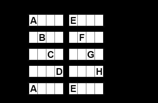
Despite a mere 25 % duty cycle and below-recommended segment current, the display is more than bright enough.
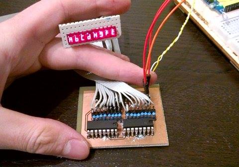
The screen assembly - before I noticed I had rotated the cathode wires on the right-most array.

Initial testing of common anode 7 segment displays. It's amazing how many jumper cables it takes!
A 400 lm, 5 W, >93 CRI LED strip!
After reading up a bit on wake-up lights and following a never-ending trail of Wikipedia articles regarding sleep, hormones, light, color rendition indeces, sunlight and how humans perceive light, I realized why those commercially available wake-up lights are so expensive. From what I could gather it seems that the effect is strongly dependent upon the quality of light, which can be quantized as the light source's Color Rendition Index (CRI). CRI is a number which in essence tells you how well a particular light-source is at revealing an objects true color in comparison to a natural or ideal light source (often referenced to sunlight). Basically: High CRI = good light. The idea behind the wake-up lights is to trick your brain that morning is coming by simulating a sunrise, and is backed by research:
Dawn simulation units mimic the gradual twilight transitions found outdoors during spring and summer. These light signals are presented to people while they are still asleep, and while their eyes are still adapted to the dark of the night. This is the point where the circadian system is most susceptible to the phase advances of gradually brightening light. The presentation of diffuse, broad-field illumination evokes an antidepressant response and helps those affected by seasonal sleep disorders to wake up normally.
Terman, M., & Terman, J.S., 2005
I decided to use
FlexFireLEDs's ultrabright series LED strip
for this project. They are indeed rather expensive, but in turn they have a guarateed CRI of 93+, a
market
best as far as I can tell. They are also very bright at around 450 lm / 5W per foot. By
comparison,
a standard 40 W incandescent bulb is 450 lm omnidirectional. I can't look directly into the
lights
at full brightness without discomfort.
These LED strips run at 12 V, so by this stage in the project I had decided to use a standard 12 V
power brick
to drive the system. Driving them is easy; A simple, generic power MOSFET connected to an 8 bit PWM
pin on the microcontroller
enabled me to dim the lights.
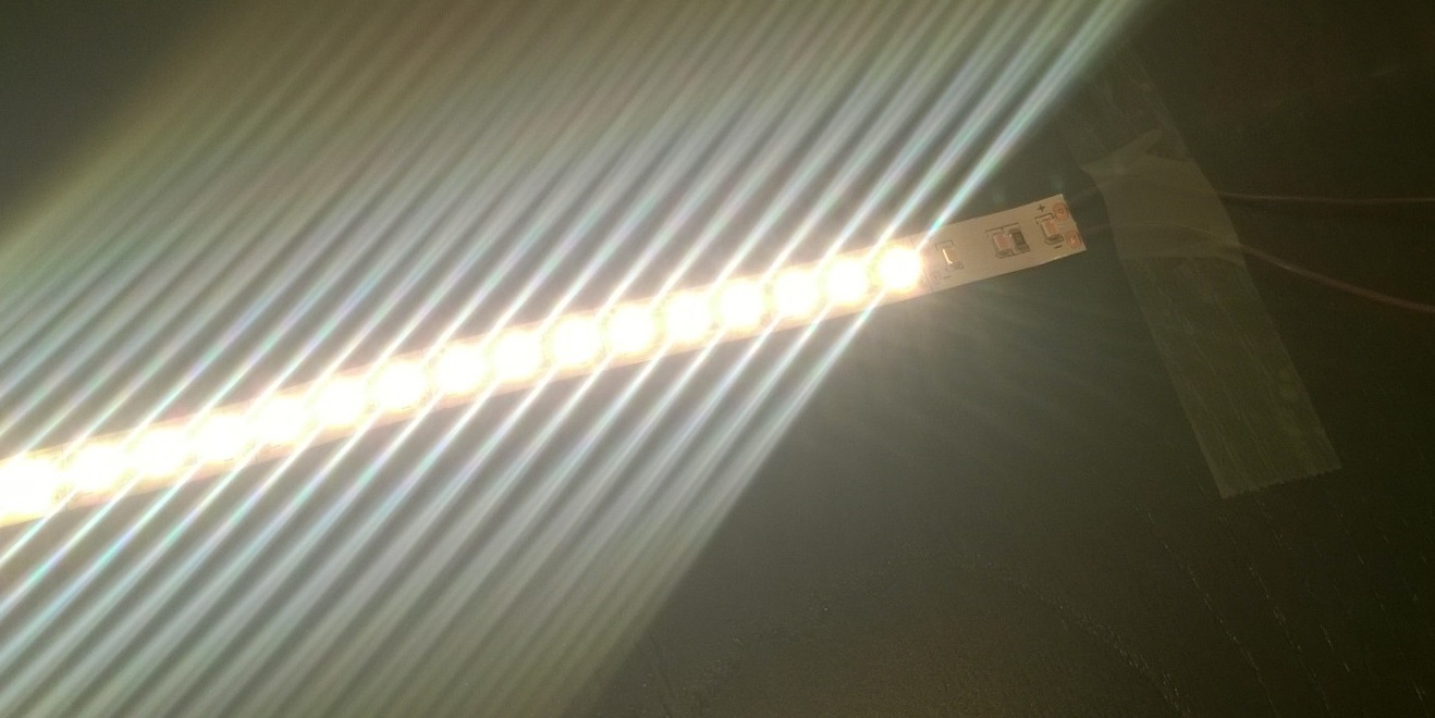
The LED strip running at around 5 % duty cycle. It's painful to look directly into the light at 100 %! Notice how the first three LED's are dead...
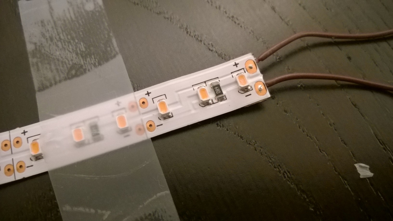
I could not for the life of me get the solder to reflow on the top of the pads, so I soldered from underneath. The heat was probably set too high, so the first row of three LED's died. This is not noticeable though -- see the section on Physical assembly.
Nixie driver board: shift registers and 180 V DC
A big thanks to
tube-tester.com for providing the ancient
datasheet for these nixie tubes!
This part of the project that had me worried for a while. The four ZM1000 nixie tubes I salvaged
require
a minimum of 170 V DC supply voltage for ignition and an average anode current of 2.5 mA. Given the
extreme rarity of
this particular nixie tube (and, surprisingly, the even rarer sockets), I was very afraid I might
damage
them by misunderstanding their parameters. Reading the datasheet carefully, I decided to leave the
primer pin floating, and supplying the anodes with 180 V DC through a 20k reistor. The voltage
source
is a cheap 180 V boost converter off eBay, but in hindsight I wish I had built my own, as the one
from eBay
has a terrible coil-whine. Wrapping it in some cloth seems to kill most of the whine until I get
around to
fixing it more permanently.
Now, sinking current at those voltages is not something your ordinary 74-series shift
register can hope handle. Luckily, you can still obtain IC's from the 1970's through eBay which do
just that.
I ordered SN74141-equivalent chips from Ukraine: MilSpec TESLA MH74141, and they work a charm. The
following
is the schematic I ended up with.
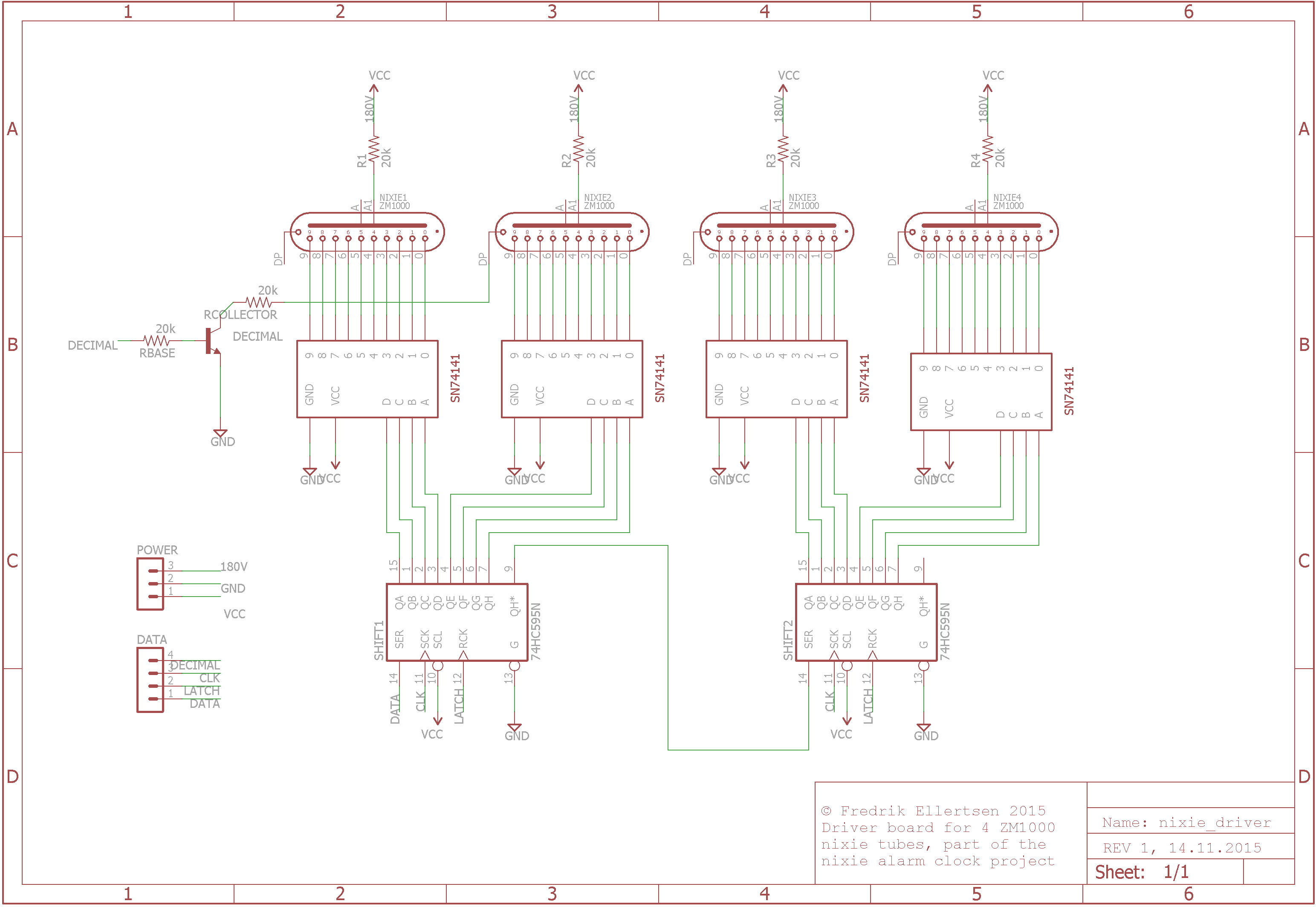
The 74141 chips are
BCD, which means
that every nixie tube needs its
own chip. Every chip has four data inputs; A, B, C and D. This adds up nicely so that four digits
can be
controlled with two shift registers. Four bits give 24 = 16 possible values, so binary
inputs of 10-15 are invalid
inputs and will result in all the outputs being high impedance -- perfect for blanking individual
nixies.
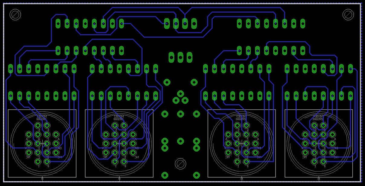
Finding an EAGLE library part for them was impossible, so I designed a package for them.
You can fetch the schematic, board layout and the library part from the bottom of this page. In
order to
pay the respect these beautiful things deserve, I decided to have the circuit board manufactured.
Feeling confident
after successfully designing the display driver board, I set about designing this one too. As with
the rest of the
system, I made sure this board too was modular, with the following header inputs:
180 V,
GND and 5 V plus DATA, LATCH, CLOCK
and
DECIMAL divided over two ribbon cables. The DECIMAL input controls the
gate
of a single high-voltage NPN transistor (MPSA42)
which sinks current from the third nixie's decimal point cathode, thus enabling a blinking decimal.
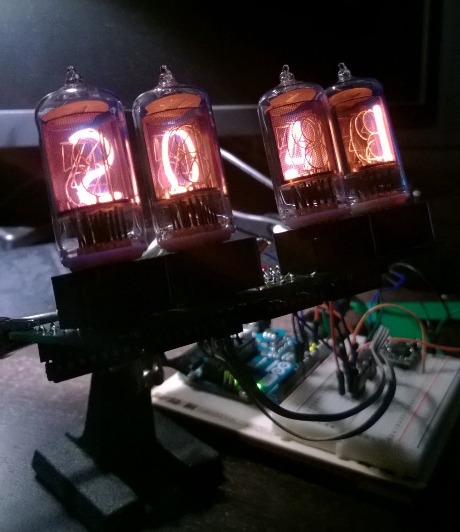
ZM1000 nixies running at 180 V DC, 2.1 mA with a 20k anode resistor. I won't say more -- just look at the sexy things.
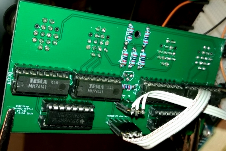
A closer look at the nixie driver. I am using header pins and ribbon cable as connectors -- cheap and easy, though unreliable. These will be sealed with heat shrink tubing later.
Bottom of the circuit board
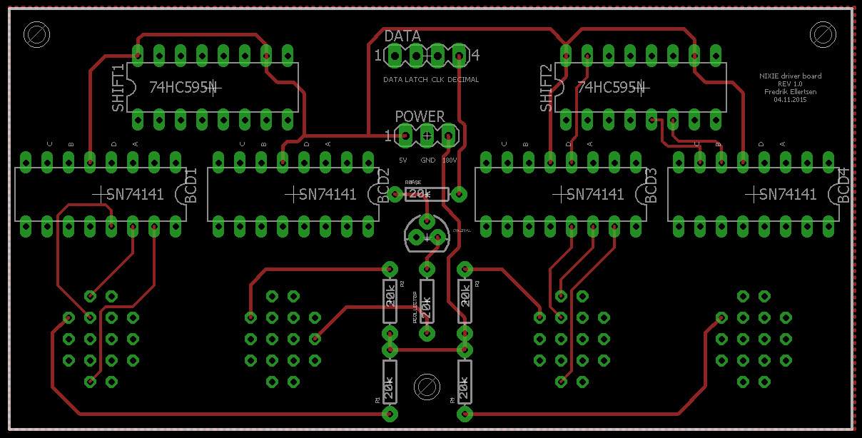
Top of the circuit board
Miscellaneous pieces of the puzzle: mcu, knobs, power supply etc.
Anticipating the everlasting work-in-progress-nature of this project, I went for perfboard for the
main
circuit board. Connectors are rather expensive, and I didn't bother ordering them
through eBay. Most of the board-to-board connections are therefore done by soldering female headers
to
ribbon cable and mating the header with a male counterpart on the PCB. This isn't the most robust
solution,
but if you make sure the solder joints are good and you add heat shrink tubing to the connectors, it
seems
to work okay for low voltage connections. I did go for proper JST connections on the power
connectors, which also
ensures I don't connect 12 V or 180 V backwards to ground or 5 V. This did happen on one occasion,
which resulted
in a lot of magic smoke and the demise of an ATmega chip and several innocent shift registers.
Luckily no
critical components were damaged.
The timekeeping is done with a breakout board based on the very accurate
DS3231 RTC
module with its own dedicated
button cell battery. The system is powered by 12 V from a (rather large) random power brick I had
laying around.

Layout of the main perfboard.
The heart of the project: Code
Interrupts and timekeeping
At first I wrote all the code in Visual Studio with the Visual Micro
plugin for an Arduino Uno, but I soon switched platforms to the
ATmega644P,
as I was interested in going deeper into microcontroller programming. This part of the project has
definitely been the most time-consuming, mostly due to the fact that I had never programmed anything
AVR,
apart from Arduino. It was a steep learning curve, but I am glad I didn't give up along the way.
The code definitely shows that I am new to this game, but at least it works!
I won't go through every line (if you have any questions or feedback, feel free to
contact me), but I'll explain key features.
Everything in the code is interrupt-driven. On the ATmega644p there are three timers; two 8 bit
timers and one
16 bit timer. The 16 bit timer is used in CTC mode to interrupt every second, calling an ISR every
time the counter reaches
the preset value in the ORC1A register. I derived the following formula from the
datasheet
to calculate the overflow compare value:

where fclk is the system clock frequency (16 MHz),
N is the prescaler value (1024) and fISR is the
interrupt frequency (1 Hz). For these values I get OCR1A = 15625. The theory behind
timer interrupts in AVR has been described exhaustively in numerous tutorials, blogs and posts
around the web, so I will not go into detail about it here.
Display code
In the file display.cpp, you'll see that the class Display has a member
function,
refresh(), which is called every 1/100th second
by another timer interrupt. This function cycles the displayed character as illustrated above. The
function
updateString(char* newStr) generates a string of bytes which is compatible with the
configuration
of shift registers
based on the c-string newStr and a long lookup-table found in header.h.
Nixie digit code
The code which handles the nixie tubes resembles the one controlling the display, but with the added
need for
decimal - BCD conversion. Every 15 seconds the microcontroller fetched the current time from a
DS3231
RTC module.
If one minute has passed, the function Clock::refresh() takes the global variables
seconds,
minutes and hour and generates BCD values for the shift registers. It also
accounts
for whether or not the user wants to print leading zeros and if he/she wants the decimal point to
flash. All this is
done on lines 30 and 31 in Clock::refresh() by the two ugliest lines of code I have
ever written --
but they work. Note to self: don't code after 3 a.m.
Rotary encoder: decoding and debouncing
Quadrature rotary encoders are knobs you can turn infinitely, as opposed to a potentiometer. They
are also digital by
by nature, and are therefore very well suited for simple menu interactions and so on. After studying
Nich
Fugal's very detailed
walk-through on how they work and how you can use them with an Arduino, the setup was easy. The
encoder I use
also incorporates a push-button in the encoder shaft. In encoder.cpp you'll find the
function
Encoder::readEncoderPosition() which is adapted from Nich Fugal's blog post. This
function both
debounces the encoder inputs A and B and calculates the probable direction in which it was turned.
Pulse-width modulation of the LED strip
Timer0 of the ATmega was configured for fast-PWM and toggles PB3 (OC0A) on compare
match with
the OCR0A register. Thus, by changing the value of OCR0A, we change the
duty cycle
of the PWM signal which drives the LED strip. As you might know, humans perceive the world mostly on
a
logarithmic scale, while microcontrollers are most definitely linear in every digital
aspect. To compensate
for this I decided to let the user choose between an exponential and a linear basis for dimming the
light. The function
Light::initializeLists() generates two lists containing respectively linear PWM values
and
exponentially spaced PWM values. Unfortunately, due to the properties of exponentials and the 8 bit
limitation
of OCR0A, the latter list contains a mere 41 steps. This results in a rather jagged
dimming of the light,
but at least it looks linear. I just occurred to me, though, that a sunrise might follow
neither
of these patterns. I promise to look into which patterns produce the best effect and post my
findings.
On a side-note: Inducing lucid dreams!
Having been intrigued by the concept of lucid
dreaming
for a long time, I now finally have equipment which enables me to induce a lucid dreamstate.
Research does back this method of inducing a lucid state. In one study, flashing lights were
administered
through goggles worn by the sleeper, inducing lucidity 33 times over a total of 58 nights with 44
subjects
(LaBerge, Levitan, Rich, & Dement, 1988). Oh yes.
This is not something I have been able to refine yet, though. What separates my crude experiments
from the
study is that they had sensors detecting eye movement through the sleeper's eyelids and activated
the
flashing lights only during REM sleep. I am still only smashing rocks together, but I have
had promising
results. For a couple of weeks I have set the alarm clock to flash the LED strip at around 05.00
a.m.
On at least two occasions the flashing has resulted in terrifying nightmares in which I was sure the
world
was ending and I was going to die (the lights being accompanied by thunderous noises,
interestingly), though
not resulting in a lucid state as far as I can recall. I will play around with the light intensity,
the
flashing frequency and the time interval during which the lights flash and post my findings.
Update: I am designing a wearable system which, using electrooculography, will be able to
detect REM
sleep. Through the use of light stimuli provided by the wearable, I will hopefully be able to induce
lucid
dreams. Click here to read more!
Physical assembly: Oak, plexiglass and excellent light diffusion
At this point I'm several months into the project and I am very anxious to collect everything and
install it
in a permanent box. Having dry-fitted the system in a suitable cardboard box for longer than I care
to admit,
I went down to my local hardware store and purchased a length of solid oak shelving
(15 by 3 cm), an acrylic sheet, decorative molding, some tools, miscellaneous screws, angle brackets
and so on.
Loosely following the dimensions of the cardboard box I constructed a basic shape. The top plate is
screwed in from
the sides, and the plexiglass front can slide out.
I drilled undersized holes in the back plate and hammered in PCB spacers in order to fasten the
three circuit boards,
which is surprisingly sturdy. The arm switch and the rotary encoder are fastened with nuts through
the plexiglass.
Fastening the LED strips to an angled wooden molding which spans the entire width of the box
I keep the inside of the box shielded from the light as well as directing the light outwards. Using
very fine
sandpaper I diffused the bottom of the plexiglass in order to hide the LED strip as well as
spreading the light.
This worked really well; It hides the fact that the light consists of several small LED
modules without
compromising brightness or light quality. It is, however, important to polish vertically, not
horizontally.
If the minute grooves in the acrylic material from the sanding are parallel to the LED strip, the
resulting
effect will not be diffusion -- rather, you will reinforce the feeling of the light being
"one-dimensional".
Having designed this system without the assembly in mind, everything was a mess of ribbon cables.
The highly modular
nature of the system is one of the reasons why the box is so large. In order to clean up the mess of
cables
I stripped some thick copper wire and shaped it into a hook. The shape became
quite rigid after applying loads of solder. Fastening it to the bottom plate of the box I was able
to
secure the display right behind the plexiglass as you can see in the image to the right. Not only
does this
look cool, but it allows much more insight behind the display than what you would have if the
display was
fastened to a large PCB. I made another hook for cable management inside the box.
Final polishing was done with coarse sand paper and extra virgin olive oil. I hope my clock won't go
rancid
on me.
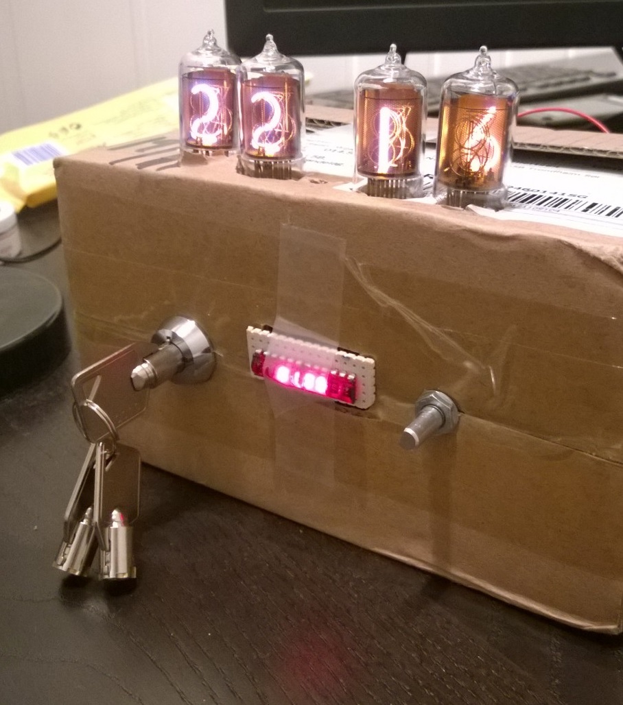
Dryfitting the system in a cardboard box.
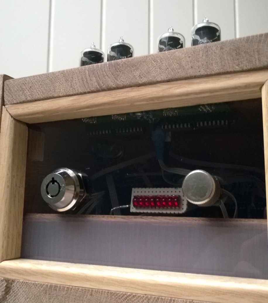
A look through the transparent front. You can see the how the plexiglass is polished: Vertically, not horizontally
Links and downloads
-
Full source code: download .rar
-
Board schematic EAGLE files: download .rar